Verifying Monaurally and Binaurally Linked Telephone Programs

Telecoils have been a long-established option for supporting telephone use with hearing aids, and although typically thought of for use with landlines only, the Federal Communications Commission requires that cell phone carriers offer a selection of devices with telecoil strengths considered to be hearing aid compatible (Ratings T3, and T4). It is true there are newer Bluetooth and 2.4 GHz- based technologies available to assist with telephone communication, particularly with cell phones; however, according to a Statistics Canada survey from 2013, more than half (56%) of Canadian households continue to use traditional landline telephones. Similar statistics are seen in the United States where the Centre for Disease Control/National Heath Survey showed up to 51% of US households continued to have landlines.1 Further, although 83% reported having an active cell phone in Canada (91% in the US), only 6% aged 55 and older in Canada, and 19% aged 64 and older in the US, used cell phones exclusively.1,2
Despite “hearing on the telephone” being rated as “important” to 92% of hearing aid users surveyed in MarkeTrak VIII,3 the level of satisfaction of hearing aid users when talking on a phone (including cell phone) was still rated among the lowest compared to other listening situations in MarkeTrak IX.4 From the nineteen listening situations listed in MarkeTrak VIII, only “one-on-one” and “small groups” were rated important by more consumers than hearing on the telephone; however, Rogin and Abrams report only 59-69% of hearing aid owners were actually satisfied with their hearing aid when talking on a traditional telephone and only 59–70% were satisfied when talking on a cell phone depending on the age of their hearing aid.5 These low satisfaction numbers support (a) experts who argue that telecoil programs, which are frequently based on the response of the main listening program of the hearing aid, may be too weak to provide a clear audible signal on the telephone, particularly if the aid is unverified, and (b) careful selection and verification of both acoustic and telecoil programs may help to increase user success and satisfaction.6–10
Hearing health care professionals have access to standardized, coupler-based verification of telecoil strengths (ANSI S3.22-2009); however, these tests are often run using manufacturer settings for quality control check purposes according to ANSI/IEC settings rather than the user’s settings. Valente argues that for the telecoil to provide maximum benefit, clinicians must pay as much attention to the telecoil frequency response as they do the microphone frequency response.9 Because the output of the hearing instrument can vary depending on the relative orientation between the magnetic field and the telecoil, verification of the telecoil response in the actual use position is preferred,7 and this idea is reinforced in the AAA guidelines for Audiologic Management of Adult Hearing Impairment which state that “The telecoil output should be verified given the presentation angle of the desired signal. In-situ measurement simulating the desired condition may be necessary to obtain the most accurate results.”11
In the sections below, we describe one specific system that has been purposed-designed for use in real ear (REM) and simulated real ear (SREM) verification of telecoil output at the user’s settings. For the purposes of this article, we will focus on the application of the system to evaluate and fit to maximize audibility of the telecoil signal for telephone use, rather than the device’s other capability of testing the telecoil strength for ANSI/IEC quality control purposes or audibility evaluation of the telecoil signal for loop systems.
Using the Audioscan Verifit2 (VF2) to Test the Telecoil-Based Phone Program
The Audioscan VF2 includes several specific features that can be used together to create a clinically feasible verification system for telecoil-based telephone programs in hearing aids. Testing of the telecoil for telephone programs can be done at the individual patient’s settings, and can be assessed for speech test signals, allowing a valid assessment of output even when adaptive signal processing is present in the hearing aids. Features of this system include: (1) a tele-test handset (Figure 1), which provides an inductive stimulus and can be held in a realistic telephone use position; (2) options to assess binaural output on-ear or in the test box on the couplers; and (3) monitor headphones (Figure 2) that allow the clinician to hear the output of each device being measured, facilitating assessment of signal transmission and clarity during fitting and fine tuning. We’ll describe each of these components below, and then illustrate their combined use with case examples.
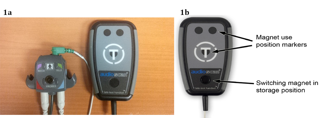
Figure 1A and B. The tele-test Handset developed for use with the Audioscan Verifit2. The figure on the right illustrates the magnet which can be moved to the various position markers for use with hearing aids with autocoil function.
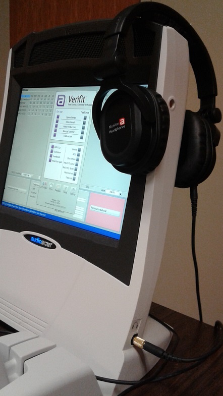
Figure 2. Monitor headphones of the VF2.
The Tele-Test Handset
The tele-test handset is a hand-held accessory designed for use with the Audioscan VF2. It can be configured to emit an inductive signal, or telefield, equivalent to a 65 dB acoustic stimulus (56.2mA/m). This device can be used during real ear or simulated real ear to verify the telecoil response (as recommended by Valence).9 Although not the focus of this article, it is worthwhile to note that the tele-test handset can also be used as a telephone magnetic field simulator (TMFS) to perform ANSI tests and was designed according to ANSI S3.22-2009 standards.
In Figure 1A, the connection from the main system to the tele-test handset is shown. The green connector plug from the tele-test handset cable attaches to the neck-worn probe dock, allowing the device to be easily positioned in the telephone use position during test-box or on-ear testing. The tele-test handset is shown on the right. The encircled “T” marks the main emission zone of the telefield. The black circles represent the potential positions of an optional switching magnet which are used to trigger autocoil functions Figure 1B.
Binaural Coupler and Binaural Real Ear Measures
The VF2 can measure the output of the left and right hearing aids simultaneously. This functionality has the potential to facilitate faster verification, because both hearing aids are measured at the same time. For telecoil programs, this binaural measurement capability has the added benefit of helping the clinician ensure binaural hearing aid features, such as binaural streaming of the telephone signal, are functioning properly.
Listening to the output from both hearing aids using the monitor headphones as the binaural measurement is being conducted allows for fast confirmation of device function, including autocoil activation and wireless streaming of telecoil input from the phone ear to the opposite, non-phone ear as will be described in the next section.
Monitor Headphones for Troubleshooting and Counselling
Monitor headphones are provided with the Audioscan VF2 (Figure 2) which allow the clinician to listen to the output from the hearing aids, at a comfortable volume for the clinician, while the hearing aids are in either the patient’s ears or mounted on the binaural coupler set. Clinicians can use the headphones to monitor and address patient concerns regarding sound quality across hearing aid programs as well as confirm activation of any autocoil feature and counsel on the best position of a telephone handset for maximum sensitivity / audibility. The clinician can toggle the listening condition of the monitor headphones between mute, binaural, left-only, or right-only using the wireless mouse. The default listening mode for the monitor headphones is binaural, sending the left hearing aid’s output to the left earpiece, and the right hearing aid’s output to the right earpiece. If a binaural feature, such as a streamed telecoil output, is present in the hearing aid, the clinician can use the headset to confirm that wireless transmission of the signal is successful. The mouse wheel can be used to adjust the headset volume to a comfortable level for the clinician, which is useful when listening to hearing aids of various output levels.
Step-by-Step Verification of the Telecoil-Based Phone Programs using Real Ear Measurement
The following is a step-by-step protocol that can be used to verify the telecoil response in the telephone program of the hearing aid and facilitate matching of the telecoil output to the acoustic microphone response for an equivalent input level using REM. Later, we will also discuss the setup for SREM in the test box couplers. Matching the telecoil to a prescriptive target using REM or SREM provides higher speech understanding and preference rankings.6 Although additional fine tuning may be needed at follow-up appointments, ensuring transparency between the microphone response and the telecoil response as measured on the patient’s ear is a good way to initially set the telephone program to meet the goal of a seamless transition when switching between the acoustic microphone and telecoil programs.9
Readers who are unfamiliar with REM and SREM hearing instrument measurements using the VF2 are directed to the Verifit VF2 User’s Guide available at Audioscan.com and the Audioscan YouTube Channel https://www.youtube.com/user/RealEarMeasurement/videos. Three videos provide particularly useful information for this protocol:
- Probe Tube Placement: https://www.youtube.com/watch?v=m4VkK0OAbMw
- Verifit 2: Coupling hearing instruments in the binaural test box. https://www.youtube.com/watch?v=vOAq39Tfb1Y
- Simultaneous Binaural Verification on the Verifit2: https://www.youtube.com/watch?v=6dNSoTfqryg
Step One: VF2 and Hearing Aid Setup
Set up the VF2 for verification using the same procedures you would follow for real ear measurement in Speechmap®, including inputting the audiogram and real ear to coupler difference (RECD) (measured or average), as well as the choice of prescription target. For this discussion, the target will be DSL v5.0 Adult. Connect the hearing aids to the manufacturer’s programming software and program the hearing aids to include all required acoustic programs as well as a telephone program that offers a telecoil option for receiving inputs from a landline telephone and cell phone (T). Program the telephone options (e.g., autocoil vs manual activation; T vs MT) based on the needs of the hearing aid user.
Step Two: Real Ear Measurement Setup
Prepare the patient for REM using traditional techniques.
Step Three: Hearing Aid Programming and Verification of the Acoustic Program
With the hearing aids still connected to the programming software, switch into the main acoustic program. Link the hearing aid programs so that fine tuning to target with the main acoustic program carries over to the other programs including the telephone program. Using the VF2, play one of the standard speech signals (e.g., standard female, standard male, or ISTS) in Test 1 at 65 dB and fine tune the acoustic program to match the DSL v5.0 Adult target. The standard signals have been designed for target matching and have the appropriate signal level and spectrum expected by the fitting formulas. Once the hearing aids have been fine-tuned, record a measurement.
Step Four: Hearing Aid Programming and Verification of the Telecoil Program
Unlink the hearing aid programs in the manufacturer’s fitting software and select the telephone program. Select Test 2 of the VF2 and play the same standard signal from Step 3. Use the “Level” drop down menu to choose tele-test (65) (Figure 3). This will result in an inductive signal from the tele-test handset equivalent to a 65 dB SPL acoustic stimulus when positioned close to the hearing aid. Choosing the same standard speech signal presented at “65 dB” for both the acoustic and telecoil measurements will allow for matching the frequency response for the telecoil to that of the microphone as recommended by Valente, 2013.9
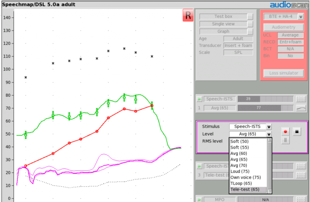
Figure 3. Menus for stimuli and level to run the Tele-test handset
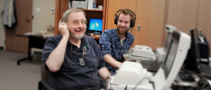
Figure 4. Running a tele-test measure.
Put on the monitor headphones and have the patient hold the tele-test handset against the ear with the front face of the handset parallel to the height of the hearing aid (e.g., like holding a telephone handset or cellphone). This positioning will vary somewhat based on the style of hearing aid. Behind-the-ear and receiver-in-the-canal hearing aid users will hold the tele-test handset in a higher position than in-the-ear users. While the inductive signal is playing, instruct the patient to move the tele-test handset around the hearing aid and listen over the monitor headphones to ensure the patient finds the ideal position where the signal is loudest. Provide coaching as needed. Once the tele-test handset position generating the loudest output is located, click record to make a measurement of the Real Ear Aided Response of the telecoil. Adjust the gain and frequency response of the telecoil program using the manufacturer’s software to match the response of the acoustic program which was fine tuned to the DSL targets for a 65 dB input in Step 3.
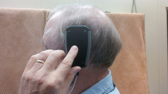
Figure 5. Positioning of the tele-test handset.
Hearing health care professionals know that positioning of the phone receiver relative to the hearing aid can have a significant impact on audibility with telecoil-based phone programs. This consideration is also true when verifying with the tele-test handset: proper positioning is key to a valid recording. The verification session can therefore be used as a teaching opportunity to allow the patient to see and hear the difference that good positioning can make, and to practice this skill. Effective counselling should also touch on aspects such as the variability in telephone magnetic fields and the associated impact on audibility as well as details regarding how to effectively access telecoil-based programs in the hearing aids (either manually or automatically).
Counselling Opportunity
Have the patient move the tele-test handset while playing the inductive stimulus to emphasize the importance of finding the best spot to hold their telephone receiver at home.
Step Five: Verifying Advanced Telephone Features
Binaural streaming of the telephone signal and autocoil activation can be verified once the fine tuning is completed and the aids are disconnected from the software as these features often do not work when the device is connected. Remember to use the switching magnets on the tele-test handset when verifying the operation of the autocoil. To verify binaural streaming of the phone program, ensure you are in simultaneous binaural verification mode on the VF2 by selecting the link L/R button in dual view Speechmap (circled in Figure 6).
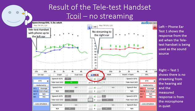
Figure 6. Binaural REM with the tele-test handset. No streaming. The left / right link button is used to activate binaural simultaneous verification mode and is circled in red.
Case Example: Streamed versus Non-streamed Telecoil Programs
The case example below illustrates the measurement differences associated with streamed versus non-streamed telecoil programs. In Figure 6, the tele-test handset was positioned over the left hearing aid, which had an active telecoil program. The hearing aid was not programmed to stream the sound to the right ear. The green measurement curves on each screen show the REARs obtained when the inductive ‘telecoil’ signal from the tele-test handset is presented to the hearing aid on the left ear. The left ear’s monaural telecoil response is clearly present, and providing a broad audible bandwidth for this running speech signal with a telecoil Speech Intelligibility Index (SII) of 58%. This is a high enough value to support high-context speech understanding for most adults even without visual cues.12 The right ear’s response is essentially a noise floor, with a telecoil SII of 0%. Listening over the monitor headphones confirmed that no speech was transmitted to the right side.
In Figure 7, we see the left hearing aid is receiving and amplifying the signal from the tele-test handset just as it was in Figure 6, with the telecoil SII at 55%. In addition, the wireless transmission for the telecoil has now been enabled, and the measurements confirm that the transmission is successful in sending the telecoil signal from the hearing aid on the phone ear (left) to the hearing aid on the non-phone ear (right). The streamed sound has a similar overall level and frequency response in both ears. The telecoil SII has increased from 0 to 50% in the non-phone ear, and listening checks with the monitor headphones confirm that speech is transmitted to the non-phone ear side.
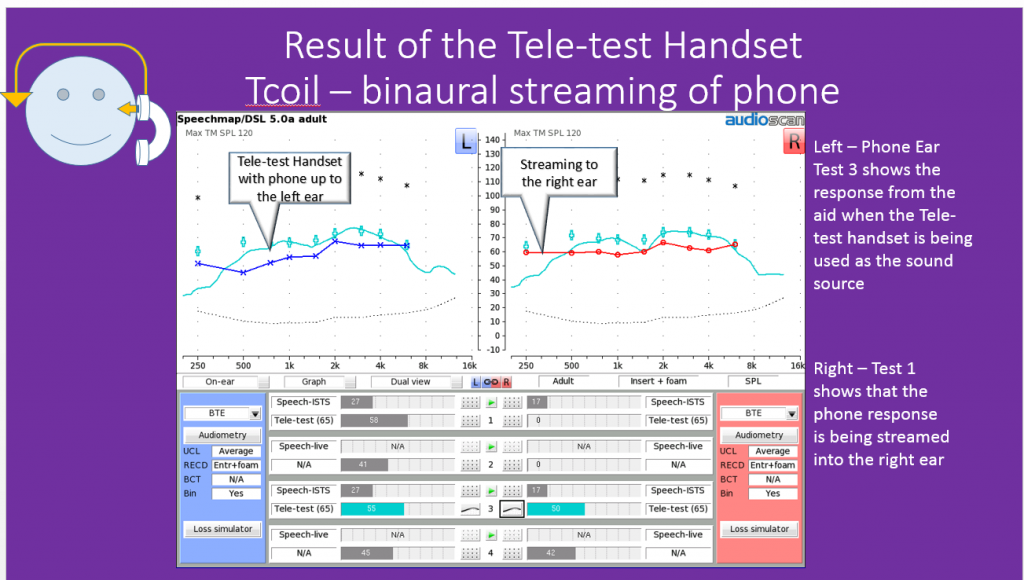
Figure 7. Binaural REM measure with tele-test handset (streaming).
The ability to simultaneously see the level and frequency response of the tele-test handset response, while measuring and listening to the signal, is a much faster method for checking this feature compared to the traditional method of using a listening tube or stethoclip to listen to just one hearing aid at a time. The monitor headphones can facilitate more comfortable listening during troubleshooting for the clinician, particularly if the hearing aids are set to provide high levels of gain/output, because of the headphone volume control. Most importantly, in our experience, the phone verification tools and techniques described allows the clinician to work together with the hearing aid wearer to adjust and fine tune the sound coming into both the phone and non-phone ear to obtain and verify a good level of balance, loudness, and clarity.
Tips and Tricks for Telecoil Measurement
The step-by-step protocol above outlines a number of key verification considerations with telecoil-based phone programs. In a recent study using this system, we discovered a few helpful tips and tricks that can further improve measurement reliability and help with troubleshooting. Here are a few ideas to consider:
Tips on Signal Transmission and Movement Noise
- Ensure that the tele-test handset stays stable throughout the measurement. Movement during the recording can add microphone noise (if the telephone program has an active microphone). Keeping the monitor headphones on during the recording, and listening for movement will help you identify and troubleshoot any movement issues.
- Although the tele-test handset is emitting an electromagnetic signal, the probe tube microphone is measuring all sound in the ear canal. As with any on-ear measurement, minimizing room noise and asking the patient to remain quiet during the recording is important.
- If the hearing aid uses a mixed microphone and telecoil input in the telephone program (a common option), remember that both inputs are active. The tele-test handset only provides an inductive input. During use with a real phone, an acoustic signal may also be delivered via the microphone path, depending on how the patient holds the phone and the style of hearing aid they are wearing.
- If the hearing aid has a large vent, the user may position a real phone to use vent-transmitted acoustic sound to hear the signal. Similar to the point above, the tele-test handset provides an inductive input and therefore does not assess vent-transmitted acoustic phone signals.
- In our study, the software version provided a telefield equivalent to 65 dB SPL. However, matching the test level to a typical phone output level of 76 dB SPL (Baum, 2010) could also be considered if supported by the test system's software.13
Tips on Measuring and Troubleshooting Binaurally Transmitted Telecoil Programs
The binaural measurement feature of the VF2, in conjunction with the tele-test handset, allows for verification of binaural streaming features. We found the following tests and informal measurements to be useful when working with hearing aids that wirelessly transmit the telecoil input from the phone ear to the non-phone ear:
- With the binaural verification mode activated on the VF2, present an inductive signal from the tele-test handset to the hearing aid on the phone ear. If the wireless transmission is working, you should clearly hear a signal on the non-phone ear side when listening through the monitor headphones. Further, the measurement curves on the Speechmap screen will provide evidence of streaming behaviour and documentation of the level of aided audibility. Figure 8 illustrates the differences associated with streamed versus non-streamed telecoil programs. This tip is particularly useful if wireless transmission is weak, and troubleshooting of the transmission itself is the goal. It is also useful when demonstrating the wireless transmission feature, and counselling on the patient’s preference for the feature to be enabled versus disabled.
Simulated Real Ear Measures using the Tele-Test Handset - Measuring Telecoil-Based Phone Programs in the Coupler(S)
Speechmap measurements can be completed with the hearing aids in the test box (SREM) rather than in the patient’s ears (REM). Many of the steps outlined in the REM protocol are the same when using SREM including: inputting the audiogram, RECD, and choosing the prescription target in Speechmap; programming the hearing aids; and, using the acoustic response to fine tune the telecoil response. The two main differences are (1) the aids are programmed and verified while in the text box, not in the patient’s ears, and (2) the clinician rather than the patient uses the tele-test handset in the test box when verifying (Figure 8).
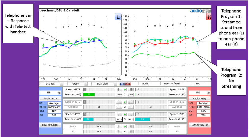
Figure 8: Tele-test measurement results with streamed (Test 1) and non-streamed (Test 2) telecoil program. In this example the hearing features were verified using SREM.
Tips for Using the Tele-Test Handset in the Test Box
- Figure 9 illustrates the correct coupler setup and tele-test handset positioning for SREM measures of BTE, ITE, and RIC instruments for both monaural and binaural fittings. Ensure that the front face of the tele-test handset remains parallel along the side of the hearing aid in order to replicate the telephone handset or cellphone position as would occur on-ear. Do not bring the handset over top of the hearing aid.
- Listening via the monitor headphones is strongly recommended during coupler-based measures to ensure proper positioning of the tele-test handset. Best reliability is obtained at the maximum sensitivity position: listen to find the loudest transmission and measure with this orientation.
- As with the REM measures, ensure that the tele-test handset does not move during the recording and that room is quiet during testing because this measure must be completed with the test box open, as shown in Figure 9.
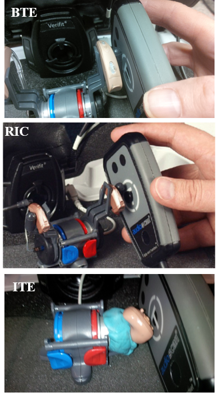
Figure 9. Coupler set up for BTE, ITE, RIC tele-test handset testing. Note the use of the magnet on the tele-test handset with the RIC. Its use allows for verification of autocoil function.
- Measuring in the coupler can be convenient for pre-setting hearing aids, for quickly checking whether features are active and working and can support binaural monitor headphone listening as well if both aids are connected to the binaural coupler microphones. However, as with any on-ear versus coupler measurement, SREM fittings can differ significantly from true on-ear measurements in fittings with large vents because the vent response is not simulated on the coupler.14 Therefore, for fittings that use larger vents, the telecoil response is best measured using REM.
Clinicians can use VF2 features to:
- Verify the telecoil program output across frequencies at user’s setting
- Listen to the sound from the aids while they are in the patient’s ears
- Ensure features such as autocoil and binaural streaming are working as expected
- Troubleshoot sound quality issues
- Counsel on telephone receiver placement challenges
But How Does the Tele-Test Handset Compare to My Patient’s Real Phone?
Agreement between the measured tele-test handset response and responses from a telephone handset were compared in a recent study.13 Measurements were obtained for twenty-one adults with mild to severe hearing loss fitted with Unitron hearing aids. Most participants were fitted with more than one hearing aid style, resulting in a total of forty binaural hearing aid fittings (BTE-18; ITE-10; RIC-12). Both real ear and simulated real ear measures were completed.
In one representative case example for a Unitron behind-the-ear style hearing aid below (Figure 10), there is a good match between the output measured from the tele-test handset compared to the response taken with the patient holding a real telephone emitting running speech calibrated at 65 dB SPL.
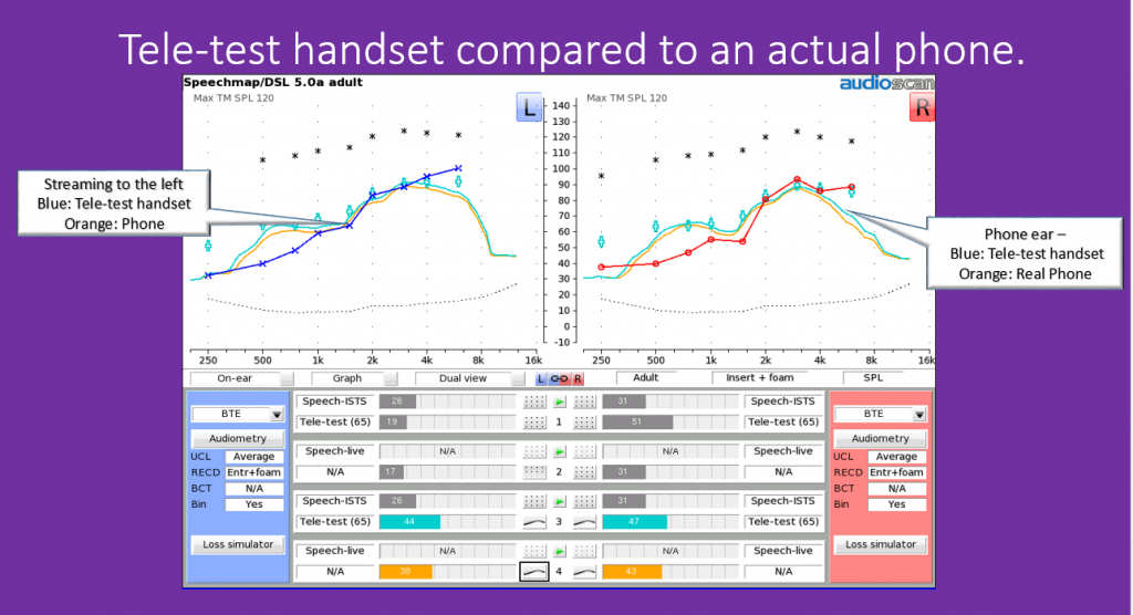
Figure 10. Tele-test handset compared to actual phone.
The study did reveal some variability across hearing aid styles and venting, as follows:
- For ITE’s (unvented), the telecoil responses in the phone ears were predicted within ±3 dB across frequencies within the phone passband and within +4 dB at 2500 Hz and above the passband of the phone. In the streamed non-phone ears, the tele-test handset slightly over-predicted the 65 dB SPL phone response, but the spectral shape was similar for both. Overall, the results suggested that the telecoil response of the phone was well predicted by the response from the tele-test handset, particularly in the phone ear.
- For BTEs, some of which had significant venting, tele-test handset responses had similar spectral shapes and were within +3 to 5 dB across frequencies in both the phone ear and the non-phone streamed ear.
- For RICs, most of which had significant venting, tele-test handset responses had similar spectral shapes to that of the acoustic phone and were within +4 to 7 dB across frequencies in both the phone ear and the non-phone streamed ear.
Overall, the study results indicated that tele-test handset REM measures represented the spectral shape of phone telecoil responses. When the tele-test (65) response was compared to a real telephone calibrated to 65 dB SPL, there was a small over prediction of level of 3 to 7 dB across hearing aid styles and venting type (Figure11).
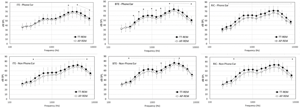
Figure 11. Results of tele-test handset (TT) vs. actual phone (AP) responses for phone and non-phone ears.
Two factors are important in interpreting these results. First, some users may have held the real phone to a position that maximized sound transmission to the vent, but then held the tele-test handset to a position that maximized telecoil-only transmission. Second, and more importantly, typical telephones can produce output levels in excess of the standard 65 dB SPL signal level, and average around 76 dB SPL. Given the variability in typical telephone magnetic field strengths, the user’s actual phone may result in a different overall output level, with higher responses from a high-quality home phone a possibility. Verification using the tele-test handset can be useful to ensure that a phone telefield response receives appropriate shaping, gain and streaming. The inclusion of multiple test levels, if supported by software, would serve to further support these verification goals.
Take Home Message
The tele-test handset provides an excellent means to measure the frequency response, gain and advanced features of hearing aid telecoil based phone programs. Although output levels of telephones vary across brands and styles, this system allows the clinician to obtain an estimate of performance with inductive phone signals using a running speech stimulus. This testing allows simultaneous binaural fine tuning of telecoil phone programs based on the measured hearing aid output curves, the aided SII, the clinician’s listening check over headphones, and the patient’s perception of clarity, comfort, and balance, all at the same time. When incorporated into an appropriate fitting and counselling regime, telecoil verification can help to ensure appropriate telecoil functioning at the individual level. This tool, paired with monitoring and follow-up, can help with troubleshooting and may contribute to increased patient use and satisfaction with telecoil-based hearing aid phone programs in their own environments by preventing dispensing of inappropriate telecoil responses.
Final Note: Set up for ANSI testing with VF2
It is worthwhile noting here that ANSI testing for telecoil strength is also completed in the test box; however, both the coupler and the hearing aid positioning are different (Figure 12) than described in the above protocol. Readers are referred to the VF2 manual and the system help menu for details on how to set up for ANSI telecoil testing.
Figure 12. Hearing aid position for ANSI telecoil tests: Note that this test uses a 2cc coupler and specific hearing aid positioning.
REFERENCES
- Blumberg SJ and Luke JV. Centre for Disease Control/National Health Interview Survey Wireless Substitution: Early Release of Estimates from the National Health Interview Survey, January–June 2015. Ottawa: Author; 2016. Available at: http://www.cdc.gov/nchs/data/nhis/earlyrelease/wireless201512.pdf.
- Statistics Canada. Residential Telephone Service Survey. Ottawa: Author; 2013. Available at http:// www.statcan.gc.ca/daily-quotidien/140623/dq140623a-eng.htm.
- Kochkin S. MarkeTrak VIII: Customer satisfaction with hearing aids is slowly increasing. Hear J 2010;63(1):11–19.
- Abrams H and Kihm J. An Introduction to MarkeTrak IX: A new baseline for the hearing aid market. Hear Rev 2015;22(6):16–21.
- Rogin C and Abrams HB. MarkeTrak 9 points the way in a time of change. AudiologyOnline 2016; Article 16512. Available at: http://www.audiologyonline.com.
- Davidson SA and Noe CM. Programmable telecoil responses: potential advantages for assistive listening device fittings. Am J Audiol 1994;3(2):59–64.
- Mueller HG. Probe-microphone measurements: 20 years of progress. Trends Amplif 2001;5(2):3–39.
- Palmer C. Ring, ring! Is anybody there? Telephone solutions for hearing aid users. Hear J 2001;54(9):10–18.
- Valente, M. The Telecoil: The lonely transducer that can be a big producer, AudiologyOnline 2013; Article 11911. Available at: http://www.audiologyonline.com.
- Sanders J, Stoody TM, Weber JE, Mueller G. Manufacturers’ NAL-NL2 fittings fail real0ear verification. Hearing Rev 2015; Available at: http://www.hearingreview.com/2015/02/manufacturers-nal-nl2-fittings-fail-real-ear-verification/.
- Valente M, Abrams H, Benson D, et al. Guidelines for the audiological management of adult hearing impairment; 2006. Available at: http://audiology-web.s3.amazonaws.com/migrated/haguidelines.pdf_53994876e92e42.70908344.pdf
- Sherbecoe RL and Studebaker GA. Audibility-index predictions of normal-hearing and hearing-impaired listeners’ performance on the connected speech test. Ear Hear 2003;24(1):71–88.
- Baum A. Conversational gain. 2010; Available at: http://ftp.tiaonline.org/TR-41/TR-41.3.5/Public/Archive/2010-Archive/2010-08-GoToMeeting/TR41.3. 5-10-08-006-L-ConversationalGain,ABaum,Uniden.pdf. [Online; accessed: 2015-06-15].
- Narten P, Pumford J, Folkeard P, Scollie S. Evaluation of the Tele-test handset and considerations for phone feature verification. 2016. Available at: http://audioscan.com/Docs/posters/2016S_poster_AudiologyNow_TTEST.pdf.